Introduction
CASTLE: Capacitor Aided System for Teaching and Learning Electricity
The CASTLE curriculum emphasizes circuits because they provide settings for hands-on inquiry that are intensely interesting for students with varied learning styles and are well suited to step-by-step model building. Teachers report that the CASTLE activities foster self-confidence and enthusiasm for physics, and that the uniqueness of these activities can “level the playing field” for a heterogeneous class. Field testing research has shown that these activities raise student confidence levels — dramatically so for females. These materials were adapted from the original CASTLE curriculum with the permission of Mel Steinberg and the CASTLE Project.
Sequencing
Unit 1 -Closed Loop Model
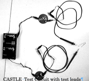
- Identify situations in which a bulb will and will not light.
- Identify the differences between conductors and insulators.
- Trace continuous conducting path in conductors and through the internal parts of a light bulb.
- Give evidence based on compass deflections to support one-way direction of flow.
- Identify and apply the definition of conventional current.
Unit 2: Charge Flow and Sources of Charge Model
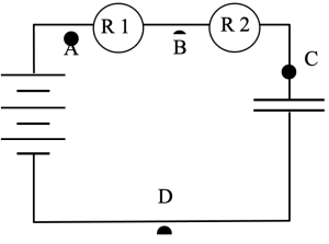
- Represent simple circuits with schematic diagrams.
- Identify the structure/parts of a capacitor.
- Indicate the direction of charge flow throughout a circuit during capacitor charging and discharging.
- Identify the places in a circuit where mobile charge originates.
- Indicate the origin of conventional charge flow in a complete circuit.
- Compare the amount of charge stored in different capacitors.
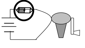
OPTIONAL – Identify, describe, and explain energy flow in a variety of circuits and with a variety of charge moving devices (battery, capacitor, genecon)
Unit 3: The Resistance Model
- Identify bulb filaments as parts of circuits that resist charge flow.
- Use bulb brightness and compass deflection as indicators of flow rate.
- Distinguish flow rate (amount/sec through) from speed (distance/sec traveled).
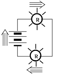
- Use representations tools to show flow rate and bulb brightness on circuit diagrams.
- Explain how adding series/parallel bulbs will raise/lower “overall” resistance.
- Describe evidence that connecting wires have much less resistance than bulbs.
Unit 4: The Compressible Fluid Model
- Cite evidence that the mobile charge in a capacitor plate can be compressed.
- Explain high/low “electric pressure” in terms of the compression/depletion of charge.
- Cite evidence that a battery creates HIGH and LOW pressure in its terminals.
- Explain why electric pressure is uniform in any wire, and in connected wires.
- Explain how a battery and wires create a pressure difference that lights a bulb.
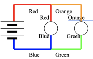
- Analyze simple circuits by color-coding conducting parts to represent electric pressure.
Unit 5: What Determines Pressure in a Wire?
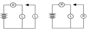
- Compare the pressure difference across a long bulb and a round bulb in series.
- Explain how steady-state pressure values arise in wires that are not connected to a battery.
- Explain why the steady-state flow rate is the same through all resistors in a series circuit.
- Describe the transient process by which the steady-state conditions in circuits arise from the initial conditions.
- Compare the flow rate through a round bulb and a long bulb in parallel.
- Analyze more complex circuits which contain a combination of series and parallel bulbs.
- Describe the effect of a battery’s internal resistance on a circuit.
- Explain what happens when a wire is placed in parallel with a bulb.
Unit 6: Measuring & Quantifying Circuit Variables
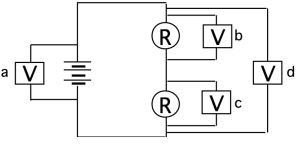
- Demonstrate that an instrument labeled “voltmeter” measures electric pressure differences.
- Identify voltmeters as having very high resistance.
- Explain why voltmeters must be connected in parallel to properly measure pressure difference.
- Demonstrate that an instrument labeled “ammeter” measures flow rates of moving charge.
- Identify ammeters as having very low resistance.
- Explain why ammeters must be connected in series to properly measure flow rate.
- Explain how to determine the resistance of an Ohmic resistor.
- Explain how to determine whether a resistor obeys Ohm’s Law.
Unit 7: Motors
- Recognize that a magnetic effect exists around a current-carrying conductor.
- The strength of the effect increases with current and decreases with distance.
- Define magnetic vector.
- Define a magnetic field as a pattern of magnetic vectors.
- Describe the motor effect: the force on a current bearing wire in a magnetic field.
- Use the Right Hand Rule for Motors to predict the direction of the magnetic force
- on charge moving through a magnetic field.
- a current bearing wire in a magnetic field.
- Describe the function of the components necessary to construct a working motor.
Sample Materials
Sample Materials Coming Soon
Interested in a CASTLE Workshop?
Workshops are offered each summer in a variety of locations. Check back often as workshops are always being added.
First-time attendees qualify for a free one-year membership to AMTA. Members have access to ALL instructional resources, webinars, distance learning courses, and other membership services!
If you would like to host a workshop contact: engage@modelinginstruction.org
